

BL40 Modulimiter
The BL40 Modulimiter from UREI is one of the old pieces Justin bought surplus and modified for modern studio use sometime around the Y2K while he was teaching himself circuit theory and design. He posted his mods on our website way back then, and quite a few people have asked to see his notes over the years. We’re archiving them here, as-is, for the handful of people who occasionally come looking for information on modding their own BL40. If you’d like to access Justin’s knowledge of optical compression but save yourself a lot of trouble, you might consider buying our RMSMC5 Valvop optical compressor module instead.
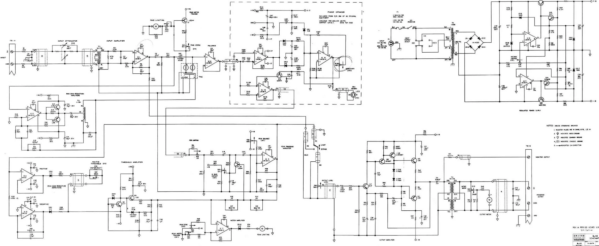
The UREI BL40 "Modulimiter" is a broadcast limiter made in the 1970s. It contains an RMS compressor, a peak limiter, and several broadcast-oriented features intended to achieve maximum allowable modulation of the audio signal. We found by carefully removing the unnecessary portions of the circuit, the BL40 could be cleaned up into essentially the circuit of a UREI LA-3A optical compressor and an 1176 peak limiter, in one box together, for less than the cost of either of those coveted vintage pieces. It seems every time we go in and pull out a few more extraneous components, the sound of the BL40 improved.
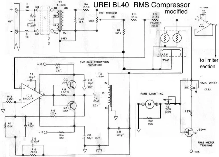
This is what we did to the input section and the optical RMS compressor. This section of the BL40 is very similar to an LA3A. We've cleaned up the signal path a bit, removing a cheap op-amp and a few capacitors as well as rearranging the gain structure. We plan to pull out a few more parts, and either remove or upgrade that one remaining op-amp.
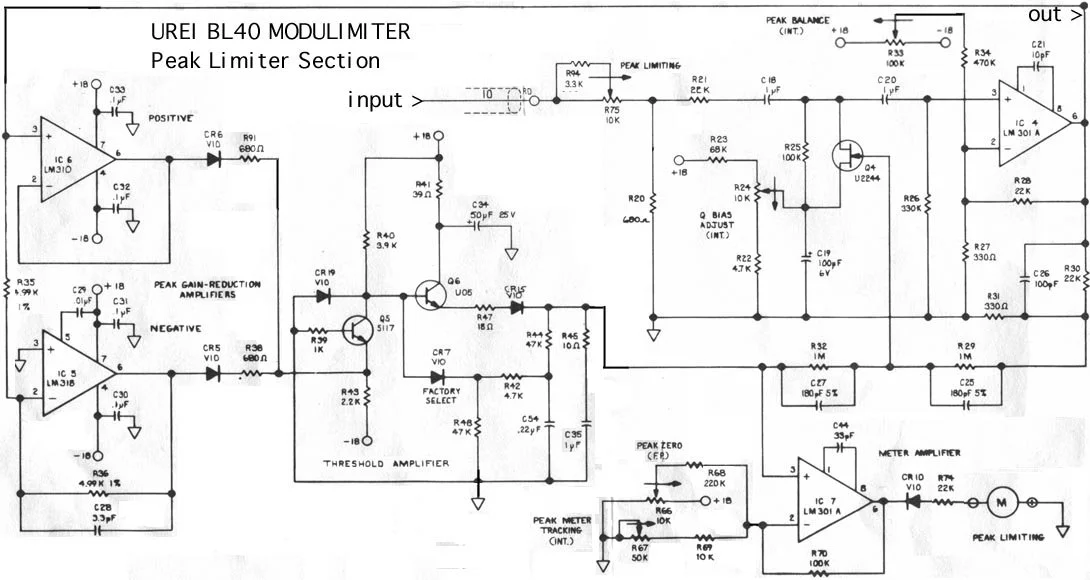
This is what we've done to the Peak Limiter. This section of the BL40 appears to be somewhat similar to an 1176. We've already removed a number of broadcast-oriented features and swapped a capacitor to change the release time. We haven't done a whole lot to this section yet. We may add controls for attack and release time and ratio. But the biggest change we'd like to make is to reduce the noise generated by IC4. Coming into the limiter section of the BL40, the signal level is greatly reduced by resistors R20 and R21, and to some extent R94 and R75. The purpose of this is to prevent the signal from overloading Q4, which is the gain reduction element. IC4 must then make up the lost gain and in doing so it generates an excessive amount of noise. We've already swapped out the old LM301A op-amp for one we found to be a little quieter, but we will eventually upgrade to a high performance op amp such as Burr-Brown OPA277. This upgrade may be sufficient to make us happy or we may have to take additional steps such as finding a way to increase the headroom in the gain control circuit (Q4 and surrounding components). This would allow us to bring a higher signal level into the limiter and reduce the gain of IC4.
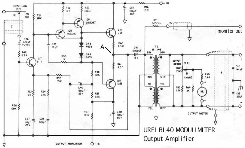
And here's the output amplifier. This section of the BL40 depicts the entire output section, from the output attenuator through the line amp, transformer and meter. We intend to get rid of that huge 2000uF electrolytic capacitor between the amplifier and the transformer (C41). This capacitor is intended to block any DC voltage present at the amplifier's output (point A) from draining through the transformer to ground. The amplifier circuit is almost identical to the output amplifier in the UREI1176 limiter, and we believe it was originally designed for the 1176 and retrofitted for the BL40. The main difference between the two is that the 1176 uses a single 30-volt power supply, making a DC offset of about 15VDC at point A, and the use of a large capacitor, inevitable. The BL40 uses a bipolar 18VDC power supply, which puts point A very near ground potential. We've measured less than half a volt DC at this point on our unit which means the polarized electrolytic capacitor will frequently be reverse-biased by the audio signal during normal operation. It's well known that electrolytic capacitors are especially nonlinear when they get reverse-biased and this is why we want to remove the capacitor. If the circuit designer wanted to, they could have modified the circuit slightly to provide for trimming away the DC and eliminating the need for the capacitor, but they apparently decided it would be easier to leave the cap in place. Since this device was originally intended for broadcast use I'm sure very few people noticed. Any competent electrical engineer should know how to trim away this offset, but since we're not electrical engineers we don't know exactly how to do it. One concern is maintaining the integrity of the design, the other is making it immune to drift during warm-up. It's not a big deal to wait for an old unit to warm up, but DC current flowing through the transformer at start-up would eventually magnetize its core and add more distortion.